 to create a sloped beam or section, you can define the sloped beams by lifting their supports.
 You may elevate or slope the top floor of your model directly in the model view. Beams can be sloped based on the Point locations of supports. You can draw beams or generate infill beams on an existing sloped area. Using the change elevated points button to create a sloped beam or section, you can define the sloped beams by lifting their supports.
The slope beams tool will lift the area based on the Selected points or beams. See Graphic Selection to learn how to make selections.
Notes:
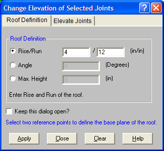
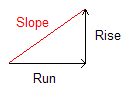
To Slope the Beams By Roof Definition Method
 on the RISA Toolbar to open a new view and click on the Graphic Editing Toolbar Icon
  to turn on the Drawing Toolbar if it is not already displayed.
 button.
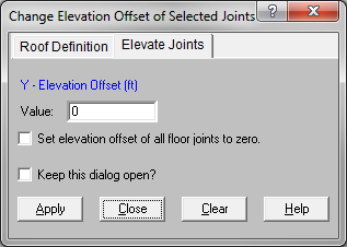
To Slope the Members By Elevate Joints Method
on the RISA Toolbar to open a new view and click on the Graphic Editing Toolbar Icon to turn on the Drawing Toolbar if it is not already displayed. button. The "Set elevation offset..." option allows you to flatten an entire floor in one click. This bypasses the sloping validation routines and is primarily useful for models that have been imported from other programs (such as Revit).
Note:
 button. Wireframe views will not show columns or walls at their elevated locations. To see this, click on the button Toggle between Wireframe and Rendering of Beams
  to enter a rendered view.
Per section 1607.11 of the 2006 IBC, live loads that act on a sloping surface are assumed to act vertically on the horizontal projection of that surface. This applies by default to LL, LLS, SL, SLN, RL, and RLL.
The dead load cases will always apply the load on the full inclined surface rather than using the reduction for projected loads.
Loads that are defined using the OL categories (OL1 through OL4) may be applied based on either the projected or inclined surface area, depending on how they are defined.
Load that are defined as Tapered Area loads may also be applied based on either the projected or inclined surface areas.
The graphical user interface (GUI) for RISAFloor was built assuming that most input would be done while viewing the floor in a typical plan view. This is true even for roof floors that will be sloped. These floors can be viewed in an Isometric view in order to visually verify the geometry. However, there are limitations to the ability of the program to display sloped floors in an isometric view.
For additional advice on this topic, please see the RISA Tips & Tricks webpage at risa.com/post/support. Type in Search keywords: Trusses.
The loading on sloped floors is always shown at the base elevation of the floor. For this reason the displayed location of Point Loads, Line Loads and Tapered are loads can be misleading when viewed from an isometric model view.
When shown in the Wireframe option for a single floor view, the columns will display at the base elevation of the floor and will not extend all the way up to their top elevation. Rendered views will show the column extended all the way up to the top of the defined level for that column. Any parapet extensions for the columns can only be viewed from the Full Model view.
Column splices are typically defined as the distance from the upper floor DOWN to the splice location below that floor. This can be problematic for sloped floors because each column can have a different elevation. For this reason, the splices at sloped floor must all be defined from the same reference point. This reference point is taken the Elevation for that floor that is listed in the Floors spreadsheet.
Refer to the section on the Columns Spreadsheet for more information about splices.
Any Points that are added to an existing floor will be created at the base elevation of that floor. During a solution the program searches for elevation discrepancies and moves those Points up to a location that matches the existing sloped beams. This is dictated based on the Global Parameter setting Move Invalid Joints on Sloped Members.
Currently you may only define sloped floors at the top floor of your building (i.e. the roof).
For the load attribution routine to be valid, every closed framing circuit must be defined by a single planar surface. If a non-planar surface is detected then the load attribution will be simplified. For these circuits the program will assume a constant elevation for load attribution. Thus, the dead load and any other loads that are not defined as projected will be applied unconservatively. A warning log message will come up at solution time for these non-coplanar circuits.
Any Point on the roof level can only exist at a single elevation. Therefore, saw-tooth roof systems cannot be modeled since they require the roof to exist at two elevations at the same column line.
The Member detail reports for sloped members will report the axial force diagrams for steel or wood members. These forces will be used in the member code check process. However, concrete beam members will neither show the axial forces nor use them in the code check.
Any weak axis shear force or bending moment that develops in members which resist the lateral thrust of a sloped member are used in the member design and code check calculations (for steel and wood). However, these forces and moments are not reported on the Member Detail Report force diagrams.
Concrete beam members are not designed for weak axis shear forces or bending moments.
Sloped floors are not allowed for Elevated Concrete Slab floor levels.